Ian Gibbins
FirstEDA

Ian Gibbins
FirstEDA
Get comfortable for more insights into achieving better code coverage
—
In part one of our look into achieving better code coverage, we introduced code coverage and code coverage types and saw that the use of code coverage can improve the quality of your verification procedures. In this part two of our three-part series, we will take a look at property coverage, covering the basic terms along with a design example.
Property coverage is a close relative of assertions (as we will see later), and which have been introduced in a previous article.
Let’s get straight in and look at the basic terms of property coverage:
To carry out any temporal check in a design we will need to employ properties:
Clocking Properties
If we are talking about properties we need to clarify that whilst in theory the time domain of temporal logic can be represented in any way you want, in practical applications (which means both PSL and SVA), we are always restricted to discrete time. Therefore we have a particular type of temporal logic that operates on sampled values of signals in a design. We, therefore, use clocking events in a design to ensure that something will happen.
PSL is very convenient and lets you set default clock using the default clock statement taking the argument of which edge to use for clocking:
default clock is rising_edge(CLK1);
If the global clock or default clock is not enough, which is possible if we have some very special properties which require fine-tune clocking, we can add the @ at the end of the property (or sequence). In such case will only be used for that particular property or sequence:
my_prop_or_seq @falling_edge(CLK2);
There are also dedicated rose() and fell() functions to detect signal edges for the purpose of “internal clocking” detecting the start of a sequence for example.
Let us now look at some very simple property examples, technically speaking they are sequences that represent the basic building blocks of properties in PSL. The semicolon represents concatenation and means that what is expressed either side is separated by one clock cycle. The curly braces are a clear indication that we are dealing with a PSL sequence.
Concatenation: This is where A is true in the current clock cycle and B is true in the next cycle:
{A ; B}
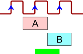
Concatenation with Consecutive Repetition: This is where A is true for 2 clock cycles and B is true for 2 clock cycles (starting at the next sample after A sequence ended):
{A[*2] ; B[*2]}
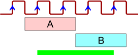
Consecutive Repetition with Range: This is where A is true for 2 clock cycles and B is true for 2 to 3 clock cycles (range) (starting at the next sample after A sequence ended):
{A[*2] ; B[*2 to 3]}
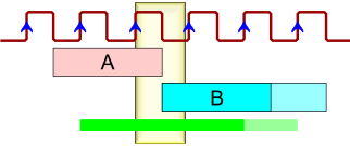
Fusion with Repetition: This is where A is true for 2 clock cycles and B is true for 2 to 3 clock cycles (starting at the same sample where A sequence ended) here we use the colon to indicate fusion:
{A[*2] : B[*2 to 3]}
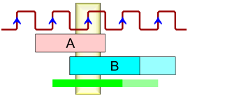
Inclosure: This verifies that the first argument (time-wise) is completely enclosed within the time period when the second argument is true. So A is true for 2 clock cycles within 5 clock period time when B is true :
{A[*2] within B[*5]}
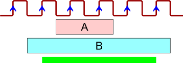
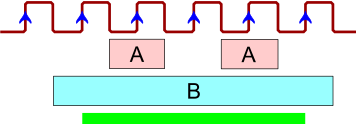
Non-consecutive Repetition: This is where A is true for 2 clock cycles (not necessarily consecutive) within 5 clock period time when B is true :
{A[=2] within B[*5]}
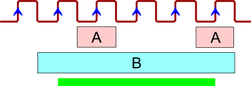
Go-to Repetition: This is where A is true for 2 clock cycles (not-consecutive, but including the last sample in sequence) within 5 clock period time when B is true :
{A[->2] within B[*5]}
Now let us look at some more advanced property examples. These are properties using temporal operators.
Operator always: This means that the property must always hold true. Signal POWER must always be high:
always (POWER=’1′)
Operator never: Similarly, we have the opposite. Signal Z should never be true right after Y:
never {Y ; Z}
Operator eventually!: Here we have ‘at some point’. Signal DONE should be true before the end of the simulation:
eventually! DONE
Here are some properties involving implication, it’s an exact copy of logical implication but it deals with temporal expressions.
Both antecedent on the left-hand side and consequent on the right-hand side can be temporal expressions that spread for more than one clock cycle.
If we use overlapping implication, we say that the consequent starts at the same time as the antecedent ended.
If we have the consequent starting in the next cycle after the antecedent, then we have the case of non-overlapping implication.
Non-overlapping implication: If X is true for 2 cycles, then Y is true for 3 cycles starting at the last sample of X:
X[*2] |-> Y[*3]
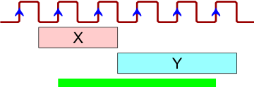
Overlapping implication: If X is true for 2 cycles, then Y is true for the next 3 cycles after the last sample of X:
X[*2] |=> Y[*3]
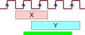
We have mentioned earlier that properties are used both in assertions and in property coverage so let us understand what the difference is.
When properties are checked with an assert directive, the simulator will alert us only when something went wrong, which is not good for coverage. We want to know when the property was exercised and not when it failed. Therefore, we must use the property with a cover directive to get confirmation that the behaviour it represents was tested.
Properties used in a cover directive enable property coverage; we will see messages when property evaluation succeeded and a report listing all properties that were not covered.
Note that properties with implication (|=>, |->) are very convenient in assertions, but not so much in covers. This is because of something known as Vacuous pass which is the situation when the implication antecedent is false which guarantees that the entire implication is true. So vacuous pass is good for assertions as it avoids false alarms, but triggers false positives in covers.
Now we armed with some property knowledge, let’s move onto a design example.
Here is an excerpt from the design specification:
Signal DVALID should be activated 3 to 5 clock cycles after activation of ACK and 2 to 4 clock cycles before deactivation of ACK.
DVALID should remain active at least 2 clock cycles after deactivation of ACK.
We need to express this behaviour in PSL by recognising that there are 3 time phases.
First phase of the property (only ACK is active):
{ rose(ACK) : (ACK=’1′)[*3 to 5] }
Second phase (DVALID and ACK are active):
{ rose(DVALID) : ((ACK and DVALID)=’1′)[*2 to 4] }
or even
{ rose(DVALID) : (DVALID=’1′)[*2 to 4] }
Third, final phase (only DVALID is active):
{ fell(ACK) : (DVALID=’1′)[*2 to inf] }
Note that code coverage would not be able to distinguish these particular situations which is why we need property coverage.
Now we need to insert the properties and we can inject PSL code into special comments in VHDL, this way it will not interfere with synthesis or similar applications.The first statement is equivalent of saying the default clock should be on the rising edge. This is followed by defining 3 sequences to represent the 3 phases of our property. You can see that we are naming the sequences for reporting and debug purposes using the signal names involved plus a suffix to mark them as sequences or properties.
The final property definition concatenates those 3 sequences to one property.
We have our property but we need to tell the tool how to check it so we add the labelled cover directive which informs the simulator how to check the property. The report part determines what message will be displayed in the console when the property is successfully covered.
–@clk rising_edge(CLK);
–@psl sequence ack35_s is { rose(ACK) : (ACK=’1′)[*3 to 5] } ;
–@psl sequence dvalid24_s is { rose(DVALID) : (DVALID=’1′)[*2 to 4] } ;
–@psl sequence dvalid2inf_s is { fell(ACK) : (DVALID=’1′)[*2 to inf] } ;
–@psl property ackdvalid_p is { ack35_s ; dvalid24_s ; dvalid2inf_s } ;
–@psl ackdvalid_c: cover(ackdvalid_p) report “Sequence ACK/DVALID covered!”;
If this is run in a simulation tool such as Riviera-PRO then you will see from the trace below some red trace which means that the property was not successfully tested and looking at actual signal values it can be seen that DVALID was deactivated too early. However sometime later at 175 ns the property bar is green signifying that the property was covered and the message stating that the sequence was covered should be visible on the console.

When developing properties it is important to note that additional simulation resources will be needed to check them, so here are some tips to minimise the extra simulation resource:
We have seen that property coverage checks functional correctness of the design by comparing its behaviour against design properties. We have also shown that property coverage requires some coding in PSL (or SVA) and access to a simulator license. When considering properties remember that 100% property coverage says that all properties you have specified were exercised, so choose them wisely! More importantly, less than 100% property coverage means that your design behaviour does not meet the design specification requirements which should ring alarm bells! Finally, properties are not just for simulation, they also work in formal verification and can be a great asset to your verification methodology.
In part three, we will conclude the code coverage journey and look at smart functional coverage and Open Source VHDL Verification Methodology – OSVVM. We will see how functional coverage can be combined with constrained random stimulus to become ‘smart’.